AMOF-Fjell Process Technology has a long history of designing, manufacturing, installing and commissioning Compact Fishmeal Plant for on-board fishing vessels. Typical plants have a capacity range of between 15 to 700 tons of raw materials per day.
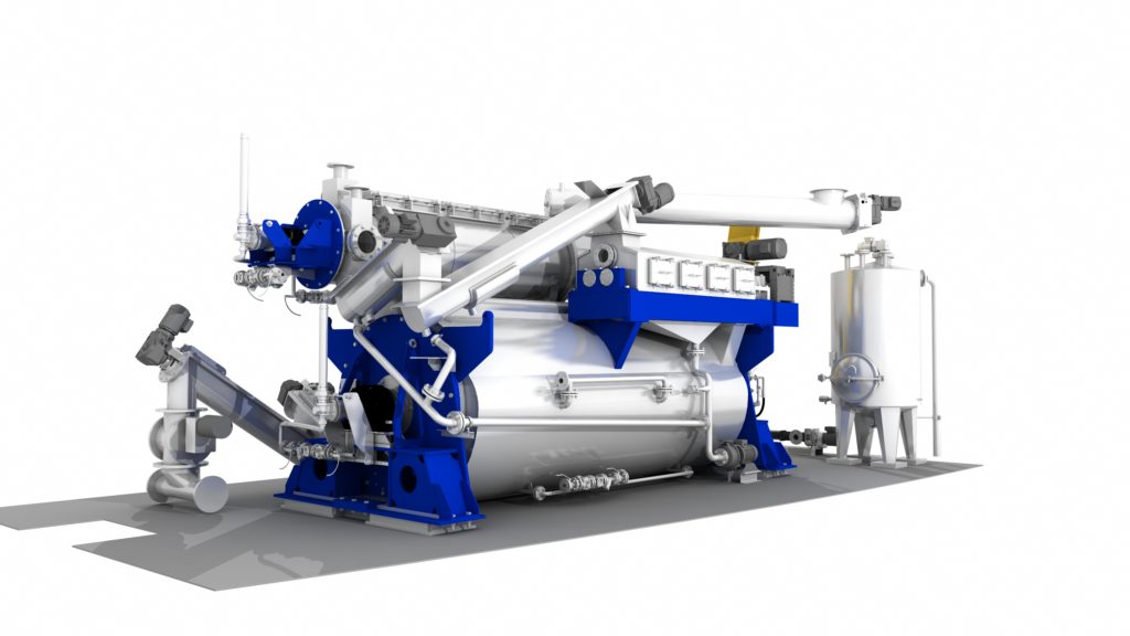
**Cooker, press, tricanter, dryer, meal mill, meal cooler and meal silo included in arrangement.
AMOF-Fjell Compact Fishmeal PlantsAMOF-Fjell fishmeal plant turns trawler waste into profitable fish products
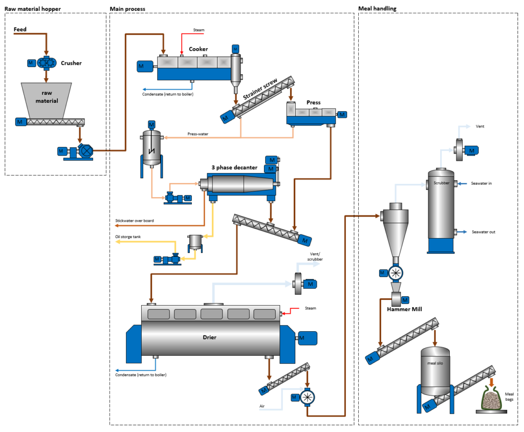
Functional Description
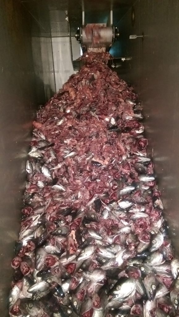
- Fish offal must be pre-treated in a way that limits the amount of free water from processing and transport in the fish factory and be coarsely ground to avoid large heads and bones, not mashed to pulp, before it is sent to the raw material hopper (storage tank not part of scope).
- From this tank the material is conveyed by a screw conveyor or a suitable pump to the screw cooker.
- The screw cooker is designed as a large slowly rotating screw conveyor with steam heated outer pipe and hollow steam heated flighting allowing heating of the raw material to about 90°C to secure complete coagulation. Additional straining of free water is recommended if screw conveyor is used.
- Coagulated material is directed by means of one or two screw conveyors (depending upon final lay-out and available height) to the twin screw press. Again additional straining (in strainer conveyor or separate strainer) will be required to minimise amount of free liquid water to the press, which may otherwise prevent complete pressing.
- The twin screw press consists of two counter rotating screws with conical shaft so that available volume between screws and the casing is gradually reduced. The casing is perforated so that liquid is squeezed out, and the press cake is dropped or conveyed directly into the dryer.
- The liquid from the press is directed to the press liquid tank together with liquids from the strainer or strainer conveyors. From this tank the liquid is pumped into the tricanter, which in one single step by means of centrifugal force is able to separate the liquid in a pulp containing the suspended solids, stick water consisting of water with water soluble proteins, and high grade fish oil. The pulp is conveyed to the dryer, the stick water is discharged to sea, and oil is pumped to a suitable oil storage tank.
- The dryer consists of a steam heated jacket (optional) and an internal rotor with steam heated hollow discs. The mixture of press cake and tricanter pulp is heated to the boiling point, and water evaporates as the material is gradually transported to the outlet of the dryer my means of agitators installed on the tip of the discs. The combination of gentle rotation and evaporations result in a fishmeal with approx. 10 % residual water.
- Vapour from the dryers is drawn out and treated in a seawater scrubber together with ventilation air and vapour from the other process equipment. (optional)
- Warm and bony fish meal is conveyed in one or two conveyors to the milling plant.
- The milling plant converts the meal to a homogenous powder.
After milling the meal is conveyed to the meal silo, which serves as the main reservoir for bagging. Transport may be by means of cooling screw conveyors or pneumatic system.
Mass and Energy Balance
Typical mass and energy balance for 100 ton raw material per day is given below. The assumed raw material composition shows a typical composition of offal from fat fish and lean fish. The total solids and fat content varies a lot from species to species and season to season. The quality of the output streams from the press will also vary. Also important are the processing steps in the fish factory onboard the vessel. In particular the type of raw material grinding process and the retention time in the raw material storage tank will have large influence on the pressing process. Smaller particles and longer retention time tend to reduce the efficiency of the press process, thereby causing lower oil yield and more liquids to be evaporated in the dryer. Careful attention is therefore needed when selecting these processes. The mass balance below is therefore only usable as guidance for what can be expected.
Feed bin
Description of Electrical and Instrumentation Systems
MCC section
- Approximately 25 motors are required. Approximately 50% will have frequency inverters.
- The panel is equipped with one main isolating switch. Customer must provide power to the terminals on this switch. At present the system is designed for motor supply voltage 3×440 VAC (±5%), 60 Hz (±2 Hz).
- The panel is designed for all motors according to a Motor List which will be finalised when the plant components have been placed.
- The panel has cable access through the bottom and has only access through the front doors.
- The panel is made of mild steel, protected by grey lacquer.
- Speed (rpm) adjustable motors normally uses a frequency inverter variable speed drive.
- Short circuit capacity for each motor starter will depend upon type of equipment being used.
- Motor control voltage is 230 VAC.
- There is an emergency stop system that will stop all machinery connected to the panel. It consists of one emergency switch in front of the panel and 2 switches for field installation.
Animation of installation in Arkhangelsk Trawl Fleet (Compact Fishmeal Plant)
PLC section
- The panel is designed for supply voltage 1×230 VAC (±5%)
- The panel will be designed according to instrument list or PID, built into the above panel, with sensors, transmitters, actuators and valves for field installation.
- Electronic analogue signals are standardised to either 4-20 mA DC or 3-wire PT100 resistance thermometer.
- The main components are:
- electronic transmitters for measuring equipment.
- 24 V DC power supply for control loops.
- computer touch screen for all man-machine communication.
- PLC computer that handles all motor start/stop and control valves.
- PLC based motor starter control system.
- PLC based motor interlocking control system, and.
- PLC based alarm handling system
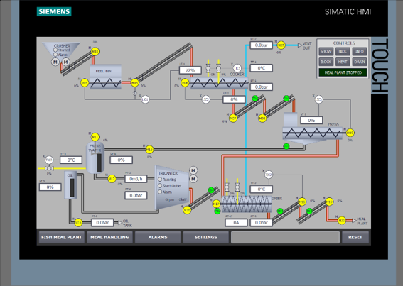
Typical HMI at AMOF-Fjell CFP plants
Field Intruments
- Temperature transmitters for coagulated material and dried product.
- Pressure transmitters for vapour vent pressure.
- Level transmitter in press liquid tank.
- Level switches in raw material hopper, cooker outlet, press inlet and meal silo.
- Scale for meal bags.
Automatic valves
- Control valves are normally 90° rotary valves, equipped with pneumatic/electric actuator and positioner or solenoid valve.
- Included (preliminary list) is two steam control valves for cooker and dryer, discharge valve for press liquid tank, closing valves for seawater and cooling water.